| |
1. |
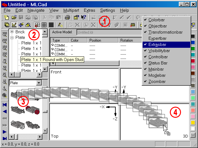
First of all we are going to tweak the interface a bit. Most of the commands and features of the program have been mirrored to the Toolbars for quick access. You'll mainly work with those, rather than the entries in the menu. The bars can be moved around, float above the interface or be docked to the borders. Move your cursor to the small vertical line at the left-hand border of the single bars, press and hold the left mouse-button and move the mouse to relocate the toolbar to a new position. Right-click the toolbars and check/uncheck the entries in the popping-up contextual menu to show or hide them. Arrange the bars as you like! The screenshot is a mere suggestion. Download the document below to get an overview of the single bars. |
 |
| |
| |
|
| |
| |
You'll notice that some buttons are grayed out as well as their equivalents in the menus are – they'll become active only after some events have happened. MLCad does not allow you to save an empty project file and therefore neither the Save button in the Main bar, nor the Save command in the File menu are accessible if there hasn't been at least one part added to the current project. |
| 2. |
The interface is divided into different areas. MLCad calls these "panes". The Parts Tree pane shows the available parts of the LDraw Parts Library in a sort of directory structure. Click the plus "+" in the tiny box to expand the tree, while a click on the dash "-" will collapse it. The sub-directories in the tree collect parts based on searching criteria. In the Brick sub-directory for example you'll find only parts which have "Brick" as first word in the part's title. Though MLCad ships with a default set of sub-directories, the parts tree is fully customizable. This is not true for three special sub-directories at the bottom of the tree, which cannot be rearranged nor deleted:
- Models lists files which are stored in the sub-directory "Models" in the program's root directory (MPD-files are not shown).
- Document contains the sub-models of a MPD-project, and ...
- Favorites contains the favorite items of the user or basic parts needed in almost every project such as standard bricks and plates or Technic pins and axles if you're a Technic buff.
We are going to add a Plate 1x1 to the favorites since we need three of them in different colors. Expand the sub-directory Plate, move the cursor above the first entry Plate 1x1 until it gets underlined and right-click. To add the plate to the favorites select Add to Favorites from the pop-up menu. Right-clicking on a favorite part (in the sub-directory containing the part as well as the Favorite sub-directory itself) allows you to remove it from the favorites by selecting Remove from Favorites. If you want to delete all parts in the Favorite sub-directory in one go just select Clear Favorites in the contextual menu. |
| |
|
Drag'n'drop |
| |
|
| 3. |
Time to add the first part to the project. Grab the slider at the right-hand side of the Parts Tree pane or use the scroll wheel of your mouse. Browse through the sub-directory until you read Plate 2 x 2 with Wheels Holder. In case the window is too narrow, hiding some of the title, use the slider at the bottom to see the rest of the part's description. You might also hover over the text which will bring forward the title in a small text box. Left-clicking the part's name will show the part in the top left-hand corner of the Parts Preview pane below. The Parts Preview pane renders a visualized version of the Parts Tree.
Press and hold the part either in the Parts Tree pane or the Parts Preview pane and drag it to MLCad's building and viewing area. |
| 4. |
The area is divided into four sub-panes showing different views of the project you are working with. This is also a place where you can add and modify parts when you are in Edit Mode. In View Mode these panes are used to show the building steps of your project. While dragging the part over the panes you'll notice that the rectangle following the cursor changes shape: It is a bounding box, showing the part's size in relationship to the selected zoom scale.
Drag the Plate 2 x 2 with Wheels Holder to the pane named 3D and release the mouse-button. Congratulation, you have just added your first part to the project!
Parts dragged to 3D are placed at the origin of the project with all coordinates at zero. This is most important for the first part to avoid any offset, which is key when your going to fly around your project in 3D later in the building process. |
| |
|
|
|
| |
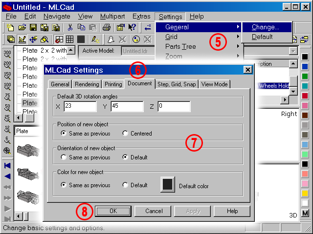
Tweaking the program |
|
| |
 |
9. |
Just to make sure we are all on the same page check if Grid Coarse  in the Mode bar is selected. If not click the button. The default value for Grid Coarse is 10 Step units on the X- and Z-axis and 8 Step units on the Y-axis. in the Mode bar is selected. If not click the button. The default value for Grid Coarse is 10 Step units on the X- and Z-axis and 8 Step units on the Y-axis.
NOTE! What MLCad calls Step units the rest of the LDraw Community calls LDUs – LDraw Units.
LDU is a basic measurement unit equal to 0.4 mm. The spacing between the centres of two adjacent LEGO studs is defined as exactly 20 LDU. With the basic ratio of 2:5, for stud-spacing to plate-height, a Brick's height is 24 LDUs and a Plate height therefore 8 LDU.
This means the parts will move 10 LDUs every time you use the arrow keys on your keyboard or the arrows in MLCad's Transformation bar. It will automatically snap to a 8 LDU grid every time you move a part up or down with the mouse. You might change the values on the Step, Grid, Snap tab in MLCad Settings dialog though 10 Step units equal a half brick-lenght distance and are ideal for fast building with standard bricks and plates with the studs ordinary at top.
Keep also an eye on the short-cut available, listed at the right of the Settings > Grid menu. Pressing F9, F10 or F11 to switch between grids is much faster than selecting them via toolbars or menus. |
|
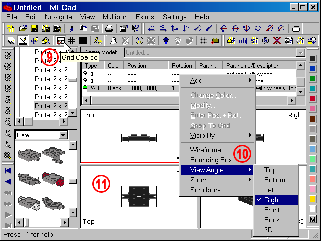
| 10. |
Make also sure the views in clockwise order starting from the top left-hand corner are: Front, Right, 3D and Top.
If you are looking at the project from different directions right-click the pane you want to change and select View Angle > (Your desired view) from the contextual menu. The pane you are going to change will be highlighted with a red border. |
|
| 11. |
A highlight will also distinguish a selected part from an unselected one. This is key, since only selected parts can be manipulated. Regardless is you select a single part or multiple parts, they will be marked with the bounding box you've already seen above. If you are requested to select a part just left-click it in one of the building area panes and make sure it gets highlighted. To cancel a selection just click another part or click somewhere in the viewing panes not containing a part to clear all selections. |
|