| [ english ] | [ deutsch ] |
|
| Home > MLCad > Tutorial: Advanced digital building - Page 2 of 5 |
| Page <Previous 1 2 3 4 5 Next> |
 |
|
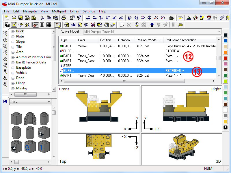
| 12. | Select the 3024 - Plate 1x1 after the BUFEXCHG command in the Project Parts List and perform a multiple selection by holding down the SHIFT key while you click on the STEP following the second 3024 - Plate 1x1. The three lines get highlighted. Ctrl+D (Edit > Duplicate) the selection. | ||
| 13. | Add a new BUFEXCHG after the STEP command but this time tick the Retrieve checkbox in the popping-up dialog to retrieve the display state saved in memory A. The description in the Project Parts List will read RETRIEVE A. NOTE! You might change the status of the Buffer Exchange command any time by double-clicking on the command in the Project Parts List or selecting Modify... from the contextual menu. At this point your project should look like this: |
 |
|
|
|||||||||||||||||||||||||||||||||||||||||||||||||||||||||||||||||||||||||
(The screenshot shows all menus and dialogs in one composed image).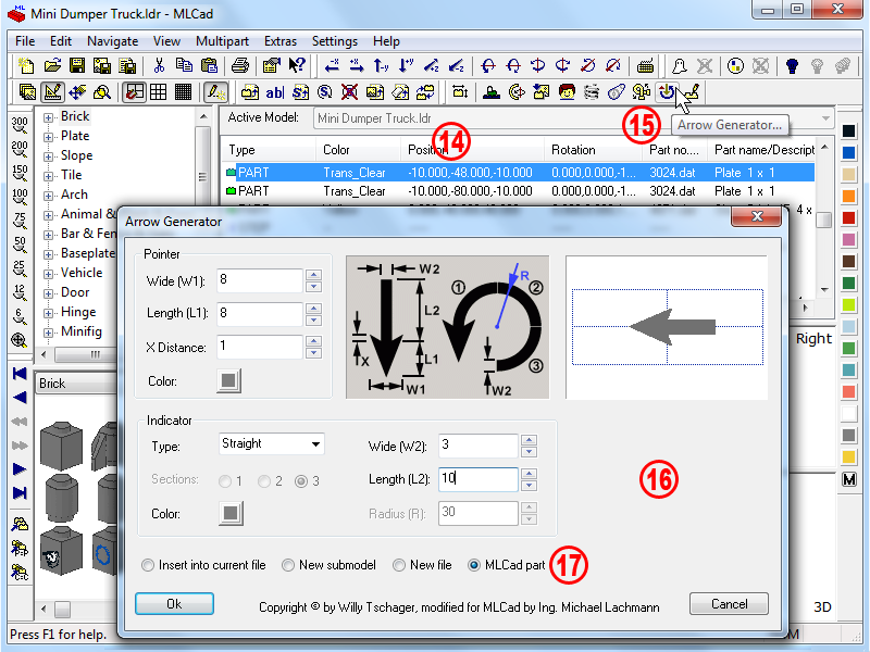 |
|
| 14. | Move the first 3024 - Plate 1x1 up by 24 LDU, the second 48 LDU and delete the STEP command prior the 3070b – Tile 1x1 with Groove in order to get the following sequence: | ||
|
|||||||||||||||||||||||||||||||||||||||||||||||||||||||||||||||||||
| 15. | Time to add an arrow which will help understanding how the plate should be positioned. Select the part after which the arrow should be inserted. Hit the Arrow Generator... button |
||||||||
| 16. | Copy the values from the screenshot above, but feel free to play around with the values first. The dialog should be pretty self-explaining. The arrow is build from so-called LDraw primitives: triangles and quadrilaterals. In case there would be an overlap because you entered very strange values, the corresponding boxes will be flagged red. Keep the left mouse-button pressed while you move the cursor in the preview window to get a feeling how the arrow will look like in a 3D environment. NOTE! MLCad offers also the opportunity to add triangle and quadrilaterals directly into the project by defining their vertices. Check out the buttons in the Expert bar By the way: LDraw part authors build parts with these basic elements. If you wanna know more about read the parts authoring tutorial Bits 'n' Pieces on this site. |
||||||||
| 17. | It is highly recommended that you leave the default MLCad part selected. It will insert a series of specific commands which make sure that the arrow will be readable by other programs of the LDraw System Of Tools and at the same remain changeable if you wanna apply some changes in a second moment. The other three options are almost identical to the one you've already seen in the Minifig Generator above:
|
| |
(The screenshot shows all menus and dialogs in one composed image).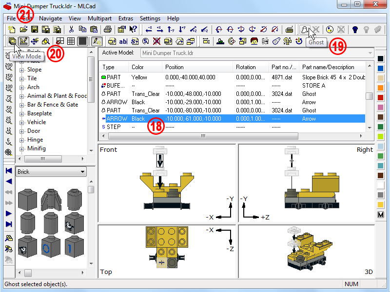 |
||
| 18. | Color the arrow part black, rotate it and position it as shown above. Copy it to the clipboard, paste it after the second plate and reposition it. | ||||
| 19. | Select all the parts – arrows included – in between the Buffer-Exchange commands and hit the Ghost button This feature is tight to the Buffer-Exchange command and has two functions:
|
||||
| 20. | Switch to the View Mode |
 |
What has happened could be summarized as follows:
|
|||||
| 21. | Finally File > Save As... Mini Dumper Truck with Buffer-Exchange.ldr. |
|
| Page <Previous 1 2 3 4 5 Next> |
|
||||
 |
Home | LDraw | MLCad | LSynth | LDView | Instructions | Wallpapers | Space | Western | Miscellaneous | About me | Sitemap | Contact |  |
||
| All content is provided as is, with no warranty stated or implied regarding the quality or accuracy of any content on or off this site. LEGO® is a trademark of the LEGO Group of companies which does not sponsor, authorize or endorse this site. |
||||
